DMDX Help.
Test Hardware
In order to thoroughly test DMDX and the
devices it will be using test hardware will need to be constructed. See Test Modes.
While an oscilloscope or storage scope (digital analyzer and so on) certainly
help the presence of a high precision timer built into modern CPUs means with a
bit of feedback from some external test hardware DMDX can do all testing that
needs to be done without external measuring devices. And while I grant in
this day and age perhaps it would be easier to just go and buy a 'scope there's
actually not a lot that can be tested without constructing at least the
photosensitive portion of this device and once you've gone that far the crystal
controlled oscillator for testing input device variability isn't much more
hassle.
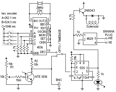
The circuit has two modes of
operation, one where it free runs using the crystal timebase and one where it
triggers from the optoisolator (depending on the switch's position.) The
banana plug optoisolator output is for hooking to the backs of switches as
opposed to using the solenoid to push them. You have to figure out which
side of the switch is ground or negative when doing so, usually just trying one
orientation then the other is sufficient, I've certainly never felt the need to
replace the optoisolator with a reed relay. Using the optoisolator is my
preferred mechanism for testing as the solenoid takes at least 11 ms to charge up
and then there's the time taken and variability incurred as the plunger
depresses. The BNC output is for hooking a scope up to as you're adjusting
the sensitivity of the phototransistor.
I've never been super happy with the
sensitivity of the phototransistor (NTE 3036), it's kinda hard to get it to trigger on LCDs and dimmer
CRTs. It's listed as a high sensitivity part so perhaps the biasing could
do with a tweak, perhaps it's load resistor R2 needs to be 22k, perhaps R1 needs
to be eliminated, perhaps the 10 meg base current limiter is too big, who knows.
I've never really tinkered with it too much because as the circuit stands it's
just sensitive enough for every use I've made of it. I recommend making
the 10k trimpot on the NTE 3036 a 20 turn device.
I've mounted the NTE 3036 in then end of a black pen cap and with a couple of suction cups it
can usually be stuck to the screen for a while. My circuit might have a
6.2 meg resistor in there with the crystal instead of the 22 meg that's listed,
don't think it makes much difference but if yours doesn't oscillate that's
probably why. The whole circuit runs off 12V DC, I've used an old
63W PC supply.

DMDX Index.