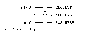

If you aren't using Windows NT, 2000 or XP
(or later OSes) the address of the PIO can either be entered as a hexadecimal value for ISA based cards,
or selected from the registry in the case of the PCI PIO cards. If you are using NT, 2k or XP you can install the InstaCal drivers that come with a Computer Boards interface cards or the wretched DriverLINX stuff that comes with the Keithley cards
(there's also some auxiliary stuff that's useful for
PCMCIA Keithley cards), then the InstaCal card number or the DriverLINX device number can be used allowing windows versions based on NT (NT itself, windows 2000 and XP so far) to use a PIO.
A recent addition in version 5.2.0 of TimeDX allows the use of the open source
inpout32 DLL and hardware driver (see below).
When listing PCI cards TimeDX under win9x OSes can't tell exactly what in the registry is an 8255 (the mere fact that it reads the registry to determine the base address of the 8255 is an extreme hack, utterly undocumented by anyone), it simply hunts for resources that describe groups of 4 I/O ports and lists them as possible candidates along with the device's description.
When using NT based operating systems only Computer Boards InstaCal cards or Keithley DriverLINX boards will be listed because using direct port I/O under NT will result in immediate protection faults. Additionally the Keithley DriverLINX stuff will have to configure the various ports on the PIO for input and output as you desire because DriverLINX doesn't let applications configure the card. Another failing of the Keitley DriverLINX stuff (it can't handle multiple threads and DMDX is massively multithreaded) would appear to mandate the use of the queued PIO devices in DMDX, the plain PIO12 device will cause DMDX to fail with the second item file run so <id QPIO12> must be used instead.
The benchmark button times how long the input and output
functions take to execute when the test is running. Overhead is a measure of
how much time is related to TimeDX executing the test itself, figures in
brackets are the times minus the overhead.
inpout32.dll
As of version 5.2.0 of TimeDX the inpout32.dll open source DLL allows direct port access on XP and later OSes, to use it you
will first need to run InstallDriver.exe in the DMDX program folder with
administrative access (right click, run as administrator) to install the ring 0 kernal mode driver interface for the
DLL. Having done that you can enter the string "inpout32.dll" followed by
the port number (in hexadecimal) you wish to output data to optionally followed
by the address of the port you wish to input data from (should you want to do
so). Most people are interested in using this to send codes to other
machines so should you wish to only input data from a port you'll have to
provide a dummy port number for it (DMDX probably won't write to it unless you
use one of the output keywords). Which begs the question, how do you find
out what port address your hardware is living on? Most devices will list
this in the device manager in the resources tab when examining the properties of
the device. Be aware that automatically assigned port addresses are liable
to change if the hardware in the machine changes in any way. Many thanks
to phil@highrez.co.uk at http://www.highrez.co.uk/downloads/inpout32/
as it's his version on inpout32.dll that we're using (he spiffed it up work with
64 bit OSes and provided the installer). He has a donate button on his
page so if you wind up using it you might want to flip him a few bucks...
For example a standard LPT1 device uses the ports 378 and up, if you wanted to output codes to the data lines of an LPT1 printer port and read the control lines for inputs you'd enter "inpout32.dll 378 379" in the PIO address box. If you just wanted to send codes to another device you'd enter "inpout32.dll 378" instead. I would note that using "inpout32.dll 378 378" is a rather handy test to see whether you've got everything working on the DMDX side of things as any output is seen on the input so as soon as you check one of the output lines the corresponding bit on the input should go low.
Note that it is critical to install the driver by running InstallDriver.exe as an administrator as it appears the code has no way of knowing that the driver isn't installed. When I was testing this I noticed that when the driver wasn't installed the data read back by the input was the same as the low byte of the address of the port, so when testing port 378 I would see LOW HIGH HIGH HIGH HIGH LOW LOW LOW which is 78 in hex. If you see that and it's not working for you it's very likely that you haven't run InstallDriver.exe as an administrator.
PIO12.
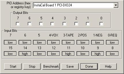
This is to verify that a MetraByte PIO-12 or ComputerBoards PIO24 has been installed correctly and is indeed functioning. The default address that Dmastr has used in the past for an ISA PIO-12 is port 310 Hex as opposed to 300H that the card ships set to. The correct switch settings for this ISA interface card at 310H read from switch 1 to 8 are OFF, OFF, ON, ON, ON, OFF, ON, ON. Clicking Start causes TimeDX to read the contents of the address edit box and setup an 8255 (the chip that is the PIO) at that address -- if you specify an incorrect address at best you will be unable to see the card, at worst you will have sent commands to some system device and the results can be catastrophic. Clicking Save writes the port address to the registry for DMDX to use.
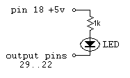
Assuming you have some test hardware and can monitor the output of PORT C clicking on the output controls changes the state of that output bit, checked being LOW (which would light a led with the test jig provided below).
The Inputs are monitored every 20 ms (in this test, for DMDX it is every millisecond), for Dmastr's usage LOW (switched to ground as opposed to pulled up to +5V) is the closed switch state.
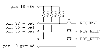
Unused inputs should be pulled up unless they are specifically disabled with the DMDX MIP word. The default value for MIP is 7 enabling pa0, pa1 and pa2, if you aren't using all of those three then the unused ones should ether be pulled up or another MIP value explicitly set in the item file.
USB PIO12 devices.
Given the prevalence of laptops these days using a USB version of
a PIO12 is becoming a more common thing. There are a few extraneous
considerations here. Firstly the USB 1.0 and USB 1.1 devices are slow to
communicate with, it typically taking 2 milliseconds to poll their inputs so
making sure you have a USB 2.0 device and a USB 2.0 port to plug it in to is
well worth it if you want the best timing available (USB 3 when it comes out
being better still). Second, using a Windows USB rate tweaker isn't going
to do anything for these devices, they will only yield improved timing on
gamepads and other standard input devices.
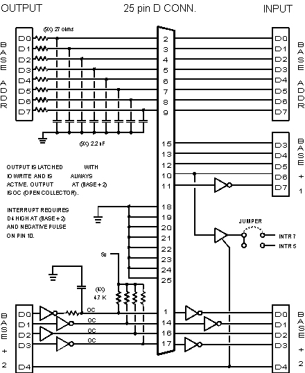
PIO12 connector.
Pinouts:

| pin 37 - pa0: | REQUEST |
| pin 36 - pa1: | NEG_RESP |
| pin 35 - pa2: | POS_RESP |
| pin 34 - pa3: | TAPE_PULSE |
| pin 33 - pa4: | VOX |
| pin 32 - pa5: | aux input Bit5 |
| pin 31 - pa6: | aux input Bit6 |
| pin 30 - pa7: | aux input Bit7 |
| pin 10 - pb0: | aux input Bit8 |
| pin 11 - pb1: | aux input Bit9 |
| pin 12 - pb2: | aux input Bit10 |
| pin 13 - pb3: | aux input Bit11 |
| pin 14 - pb4: | aux input Bit12 |
| pin 15 - pb5: | aux input Bit13 |
| pin 16 - pb6: | aux input Bit14 |
| pin 17 - pb7: | aux input Bit15 |
| pin 29 - pc0: | output 0 |
| pin 28 - pc1: | output 1 |
| pin 27 - pc2: | output 2 |
| pin 26 - pc3: | output 3 |
| pin 25 - pc4: | output 4 |
| pin 24 - pc5: | output 5 |
| pin 23 - pc6: | output 6 |
| pin 22 - pc7: | output 7 |

| pin 1 | XY1 (+5v) | (ignore) |
| pin 2 | Switch 1 | REQUEST |
| pin 3 | X1 | (ignore) |
| pin 4 | Ground | |
| pin 5 | Ground | |
| pin 6 | Y1 | (ignore) |
| pin 7 | Switch 2 | NEG_RESP |
| pin 8 | N.C. | (ignore) |
| pin 9 | XY2 (+5v) | (ignore) |
| pin 10 | Switch 3 | POS_RESP |
| pin 11 | X2 | (ignore) |
| pin 12 | MIDI TXD | (ignore) |
| pin 13 | Y2 | (ignore) |
| pin 14 | Switch 4 | VOX |
| pin 15 | MIDI RXD | (ignore) |
